
In today’s highly automated industrial landscape, accurate flow measurement is the foundation of efficient and reliable process control. Across industries such as oil and gas, petrochemicals, power generation, water treatment, pharmaceuticals, food and beverage, mining, pulp and paper, marine, and chemical processing, the ability to measure the flow of liquids, gases, and steam with precision directly impacts operational performance, product quality, safety, regulatory compliance, and profitability. Whether monitoring the movement of crude oil through a transmission pipeline, measuring steam consumption in a power plant, controlling chemical dosing in a manufacturing process, or tracking water distribution in municipal infrastructure, reliable flow measurement enables industries to make informed operational decisions.
Industrial processes depend on continuous monitoring of process variables such as pressure, temperature, level, and flow. Among these, flow measurement is often regarded as one of the most critical because it influences production efficiency, inventory management, energy consumption, equipment performance, and environmental compliance. Even a small deviation in flow measurement can lead to increased operational costs, inaccurate billing, reduced product quality, equipment damage, or unsafe operating conditions.
Over the years, numerous flow measurement technologies have been developed to address different industrial requirements. These include electromagnetic flow meters, ultrasonic flow meters, turbine meters, vortex meters, Coriolis meters, Venturi tubes, flow nozzles, and differential pressure devices. While each technology offers distinct advantages, orifice plates continue to be one of the most widely used and trusted flow measurement solutions worldwide.
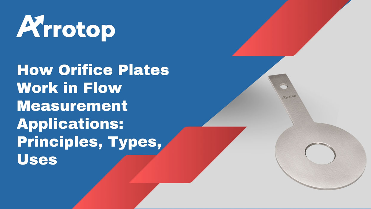
An orifice plate is a simple yet highly effective primary flow element that creates a restriction within a pipeline. As the process fluid passes through this restriction, a pressure difference is generated between the upstream and downstream sides of the plate. This differential pressure is measured using appropriate instrumentation and converted into an accurate flow rate using standardized engineering equations. Because of their robust design, absence of moving parts, ease of installation, and compliance with internationally recognized standards such as ISO 5167 and ASME MFC, orifice plates remain a preferred choice for industrial flow measurement applications.
Despite the emergence of advanced digital flow meters, industries continue to rely on orifice plates because they offer an excellent balance of accuracy, durability, simplicity, and cost-effectiveness. Their ability to operate reliably under high pressures, elevated temperatures, corrosive environments, and demanding process conditions makes them suitable for both new installations and retrofitting existing piping systems.
At Arrotop, precision-engineered orifice plates are designed and manufactured to deliver dependable performance across a broad spectrum of industrial applications. By combining advanced machining capabilities, premium-grade materials, strict quality control, and adherence to international standards, Arrotop provides flow measurement solutions that help industries achieve greater operational efficiency, improved process control, and long-term reliability.
Importance of Industrial Flow Measurement
Flow measurement is a fundamental aspect of industrial process control because it provides critical information about the movement of fluids within a system. Every industrial process that transports liquids, gases, or steam requires accurate flow data to ensure efficient operation, maintain product consistency, optimize resource utilization, and safeguard equipment.
In modern manufacturing facilities, thousands of liters of liquid, cubic meters of gas, or tons of steam may flow through interconnected pipelines every hour. Without precise measurement, it becomes nearly impossible to determine whether the process is operating within design parameters. This can result in production inefficiencies, excessive energy consumption, product losses, and safety hazards.
Why Accurate Flow Measurement Matters
Process Optimization
Industrial facilities rely on flow data to maintain optimal operating conditions. By continuously monitoring fluid flow, operators can adjust process parameters, improve production efficiency, and reduce unnecessary waste.
Product Quality
Many manufacturing processes require exact proportions of raw materials. In industries such as pharmaceuticals, food processing, and chemical manufacturing, even minor variations in flow can compromise product quality and consistency.
Energy Efficiency
Steam, compressed air, cooling water, and fuel gases represent significant operational expenses. Accurate flow measurement enables industries to monitor energy consumption, identify inefficiencies, and implement energy-saving strategies.
Equipment Protection
Improper flow conditions may lead to cavitation, erosion, overheating, or mechanical failure of pumps, compressors, heat exchangers, and boilers. Reliable flow monitoring helps prevent equipment damage and extends service life.
Environmental Compliance
Many industries must monitor emissions, wastewater discharge, and chemical consumption to comply with environmental regulations. Accurate flow measurement ensures regulatory compliance and minimizes environmental impact.
Custody Transfer
In the oil and gas industry, flow measurement directly affects commercial transactions involving crude oil, natural gas, refined petroleum products, and chemicals. Even slight inaccuracies can result in significant financial discrepancies.
Safety Enhancement
Many industrial systems operate under hazardous conditions involving high pressures, toxic chemicals, flammable gases, or superheated steam. Continuous flow monitoring helps detect abnormal operating conditions before they escalate into safety incidents.
What is an Orifice Plate?
An orifice plate is a precision-machined metal plate containing a carefully designed opening, known as the orifice bore, through which a process fluid flows. Installed between pipeline flanges, the orifice plate functions as a primary element in a differential pressure flow measurement system.
Its primary purpose is to create a controlled restriction within the pipeline. As fluid passes through the smaller opening, its velocity increases while its static pressure decreases. This pressure drop, measured across the plate, is proportional to the flow rate and forms the basis for calculating fluid flow.
Unlike many other flow measurement devices, the orifice plate itself contains no moving parts, electronic components, or mechanical mechanisms. This simplicity contributes to its exceptional durability, reliability, and low maintenance requirements.
Main Components of an Orifice Plate System
A complete orifice plate flow measurement system typically consists of:
- Orifice plate
- Orifice flanges
- Pressure tapping points
- Differential pressure transmitter
- Manifold
- Impulse tubing
- Flow computer or control system
Together, these components measure the differential pressure generated across the restriction and convert it into volumetric or mass flow rate.
Common Materials
Orifice plates are manufactured from various materials depending on operating conditions:
- Stainless Steel 304
- Stainless Steel 316/316L
- Carbon Steel
- Duplex Stainless Steel
- Super Duplex Stainless Steel
- Monel
- Inconel
- Hastelloy
- Titanium
Material selection depends on corrosion resistance, operating pressure, temperature, fluid compatibility, and service life requirements.
History & Evolution of Orifice Plates
The concept of measuring flow using a restriction in a pipeline has existed for more than a century. Early engineers observed that when a fluid passed through a narrowed section of pipe, its pressure changed in a predictable manner. This observation laid the foundation for differential pressure flow measurement.
During the late nineteenth and early twentieth centuries, industries increasingly required standardized methods for measuring steam, water, and gas flow. Researchers refined the relationship between pressure differential and flow rate through extensive experimentation.
As industrialization accelerated, organizations such as ASME, AGA, and later ISO established standardized dimensions, installation practices, and calculation methods for orifice plates. These standards enabled consistent and repeatable flow measurements across different industries and countries.
Modern manufacturing technologies, including CNC machining, laser cutting, coordinate measuring systems, and advanced metrology equipment, have significantly improved the accuracy of orifice plate production. Today’s precision-machined orifice plates achieve tight tolerances, excellent surface finishes, and sharp bore edges essential for reliable flow measurement.
Recent developments in digital instrumentation have further enhanced orifice plate systems by integrating smart differential pressure transmitters, remote diagnostics, predictive maintenance, and Industrial Internet of Things (IIoT) capabilities. Although the fundamental operating principle remains unchanged, modern orifice plate systems now deliver higher accuracy, improved diagnostics, and seamless integration with digital control systems.
Working Principle
The operation of an orifice plate is based on the principle that when a fluid flows through a restriction, its velocity increases while its pressure decreases. This pressure reduction is proportional to the flow rate and can be accurately measured.
As the fluid approaches the orifice plate, it travels at a relatively uniform velocity. When it reaches the smaller opening, the available flow area decreases significantly. Since the same quantity of fluid must continue moving through the pipe, the fluid accelerates as it passes through the restriction.
Immediately downstream of the orifice, the flowing stream contracts further to a point known as the vena contracta, where the fluid reaches its maximum velocity and minimum pressure. Beyond this point, the fluid gradually expands, velocity decreases, and part of the pressure recovers. However, because of turbulence and friction, some pressure loss is permanent.
By measuring the pressure difference between the upstream and downstream sides of the orifice plate, engineers can accurately determine the flow rate using internationally standardized equations.
Bernoulli’s Principle
Bernoulli’s Principle is one of the most important concepts in fluid mechanics and forms the theoretical basis for differential pressure flow measurement.
The principle states that, for an incompressible fluid flowing steadily, the total mechanical energy remains constant along a streamline. As a result, an increase in fluid velocity is accompanied by a decrease in static pressure.
The mathematical expression is:
P + ½ρV² + ρgh = Constant
Where:
- P = Static pressure
- ρ = Fluid density
- V = Fluid velocity
- g = Acceleration due to gravity
- h = Elevation
In horizontal industrial pipelines, elevation changes are generally negligible, allowing engineers to simplify the equation. The relationship between pressure and velocity becomes the key factor in determining flow rate.
When fluid enters the orifice restriction:
- Flow area decreases.
- Velocity increases.
- Static pressure decreases.
- Differential pressure develops across the plate.
This predictable relationship enables highly accurate flow measurement when combined with appropriate calibration and standardized calculation methods.
Continuity Equation
The Continuity Equation is another fundamental principle governing fluid flow. It is based on the conservation of mass, stating that the mass flow entering a system must equal the mass flow leaving it, provided there is no accumulation or leakage.
The equation is:
A₁V₁ = A₂V₂
Where:
- A₁ = Cross-sectional area before the orifice
- V₁ = Fluid velocity before the orifice
- A₂ = Orifice opening area
- V₂ = Fluid velocity through the orifice
Because the orifice opening is smaller than the pipeline diameter, the velocity through the orifice must increase to maintain the same flow rate. This increase in velocity produces the pressure drop measured by the differential pressure transmitter.
The Continuity Equation, together with Bernoulli’s Principle, forms the scientific foundation of differential pressure flow measurement.
Differential Pressure Theory
Differential pressure (DP) is defined as the difference between the pressure upstream of the orifice plate and the pressure downstream.
As fluid flows through the restriction:
- Upstream pressure is relatively high.
- Pressure decreases as velocity increases.
- Maximum velocity occurs at the vena contracta.
- Downstream pressure partially recovers.
- The remaining pressure difference is measured as differential pressure.
This pressure difference is directly related to the square of the flow velocity. Consequently, the flow rate is proportional to the square root of the measured differential pressure.
Differential pressure transmitters connected to pressure taps continuously measure this pressure difference and transmit the signal to flow computers or distributed control systems (DCS), where it is converted into engineering units such as liters per minute, cubic meters per hour, kilograms per hour, or standard cubic feet per minute.
Step-by-Step Flow Measurement Process
The measurement process using an orifice plate involves several sequential stages, each contributing to the accurate determination of flow rate.
Step 1: Fluid Enters the Pipeline
The process begins with the fluid flowing through the pipeline under stable operating conditions. The fluid may be a liquid, gas, or steam, depending on the application. At this stage, the fluid possesses a relatively uniform velocity profile and pressure distribution.
Step 2: Fluid Reaches the Orifice Plate
As the fluid approaches the orifice plate, it encounters the precisely machined bore that restricts the available flow area. The reduction in cross-sectional area forces the fluid to accelerate to maintain the continuity of flow.
Step 3: Velocity Increases
The accelerated fluid passes through the orifice opening at a significantly higher velocity than in the upstream section of the pipeline. The highest velocity occurs at the vena contracta, located just downstream of the orifice plate.
Step 4: Pressure Drops
According to Bernoulli’s Principle, the increase in velocity results in a corresponding decrease in static pressure. This creates a measurable differential pressure between the upstream and downstream sides of the orifice plate.
Step 5: Differential Pressure Measurement
Pressure taps installed before and after the orifice plate transmit the upstream and downstream pressures to a differential pressure transmitter. The transmitter continuously measures the pressure difference with high accuracy.
Step 6: Signal Processing
The transmitter converts the measured differential pressure into an electrical output signal, typically 4–20 mA or a digital communication protocol, and sends it to the control system.
Step 7: Flow Rate Calculation
Using standardized equations defined by ISO 5167 or ASME MFC, the control system calculates the actual volumetric or mass flow rate. Compensation factors such as fluid density, temperature, pressure, and discharge coefficient are incorporated to improve accuracy.
Step 8: Process Monitoring and Control
The calculated flow data is displayed on operator interfaces, recorded for historical analysis, and used by automated control systems to regulate pumps, valves, compressors, and other process equipment, ensuring safe and efficient plant operation.
Orifice Plate Flow Equation
The flow rate through an orifice plate is generally calculated using the differential pressure equation.
Q=CdA2ΔPρ(1−β4)Q = C_d A \sqrt{\frac{2\Delta P}{\rho(1-\beta^4)}}Q=CdAρ(1−β4)2ΔP
Where:
| Symbol | Meaning |
| Q | Flow rate |
| Cd | Discharge coefficient |
| A | Orifice area |
| ΔP | Differential pressure |
| ρ | Fluid density |
| β | Ratio of orifice diameter to pipe diameter |
This equation shows that flow rate is proportional to the square root of differential pressure.
Main Components of an Orifice Plate Assembly
A complete orifice flow measurement system includes multiple components.
1. Orifice Plate
The primary flow restriction element.
Usually manufactured from:
- Stainless Steel
- Monel
- Inconel
- Hastelloy
- Duplex Stainless Steel
- Super Duplex Stainless Steel
Material selection depends on:
- Corrosion resistance
- Temperature
- Pressure
- Process media
2. Orifice Flanges
Special flanges hold the orifice plate in position and provide pressure tapping points.
Features
- Integrated pressure taps
- Easy plate removal
- Secure sealing
3. Pressure Tappings
Pressure taps measure differential pressure.
Common Tap Configurations
- Corner taps
- Flange taps
- Radius taps
- Pipe taps
4. Differential Pressure Transmitter
Converts pressure difference into electrical output signals for monitoring and control systems.
5. Condensate Pots or Seal Pots
Used in steam and gas applications to protect instruments from:
- High temperatures
- Moisture carryover
Types of Orifice Plates
Different process conditions require different orifice plate designs.
1. Concentric Orifice Plate
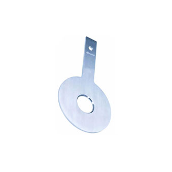
The most common type with a centered circular bore.
Applications
- Clean liquids
- Steam
- Gases
2. Eccentric Orifice Plate
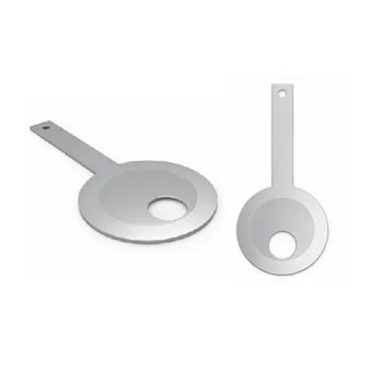
The bore is offset from the center.
Advantages
- Prevents buildup of solids or gases
- Suitable for dirty fluids
Applications
- Slurries
- Fluids containing suspended solids
3. Segmental Orifice Plate
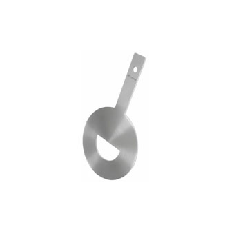
Contains a semi-circular opening.
Best Suited For
Slurries
Wastewater
Dirty process fluids
4. Quadrant Edge Orifice Plate
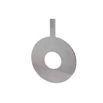
Designed for low Reynolds number applications.
Applications
- Viscous fluids
- Low flow rates
Advantages of Orifice Plates
Orifice plates continue to be one of the most widely used flow measurement devices in industrial applications due to their simple design, reliability, and compliance with international standards. Despite the availability of advanced flow measurement technologies, industries across the world continue to prefer orifice plates for a wide range of liquid, gas, and steam applications because they offer an excellent balance of performance, durability, and cost-effectiveness.
Below are the major advantages of orifice plates in detail.
1. Simple Yet Effective Design
One of the biggest advantages of an orifice plate is its remarkably simple construction. It consists of a precision-machined metal plate with a carefully designed opening that creates a restriction in the flow path. Unlike many modern flow meters, an orifice plate contains no moving parts, rotating components, bearings, or mechanical assemblies that can wear out over time.
This simplicity significantly reduces the risk of mechanical failure and ensures consistent performance even in demanding industrial environments. The uncomplicated design also makes installation, inspection, and replacement straightforward, minimizing plant downtime and simplifying maintenance procedures.
2. Cost-Effective Flow Measurement Solution
Compared to technologies such as Coriolis, ultrasonic, electromagnetic, or vortex flow meters, orifice plates offer a highly economical solution for industrial flow measurement. Their manufacturing process is relatively simple, and they require fewer components, making both the initial purchase and installation costs significantly lower.
For large industrial plants with hundreds of flow measurement points, the use of orifice plates can lead to substantial savings without compromising reliability. Additionally, the low maintenance requirements further reduce the total cost of ownership throughout the equipment’s service life.
3. No Moving Parts
The absence of moving parts is one of the primary reasons why orifice plates are known for their long operational life. Mechanical wear is virtually eliminated because the flow measurement process relies solely on the pressure difference created by the restriction.
Without gears, turbines, rotors, or bearings, there is less risk of mechanical breakdown, vibration-related failures, or frequent component replacements. This makes orifice plates particularly suitable for continuous industrial operations where equipment reliability is essential.
4. High Reliability in Harsh Industrial Conditions
Industrial processes often involve extreme operating conditions, including high pressures, elevated temperatures, corrosive chemicals, abrasive slurries, and hazardous gases. Orifice plates are capable of operating reliably under these challenging environments when manufactured from appropriate materials such as Stainless Steel, Duplex Stainless Steel, Super Duplex, Monel, Inconel, Hastelloy, or Titanium.
Their robust construction allows them to withstand severe service conditions while maintaining stable performance over extended periods.
5. Suitable for a Wide Range of Fluids
Orifice plates are highly versatile and can be used to measure the flow of various process media, including:
- Water
- Steam
- Natural gas
- Compressed air
- Petroleum products
- Chemicals
- Process gases
- Fuel oils
- Solvents
- Cryogenic fluids
Different orifice plate designs, such as concentric, eccentric, segmental, and quadrant edge plates, enable accurate flow measurement even for fluids containing suspended solids, slurries, or highly viscous liquids.
6. Wide Pressure and Temperature Capability
Unlike some flow measurement technologies that have limitations under extreme operating conditions, orifice plates can function efficiently across a broad range of pressures and temperatures.
They are commonly used in applications involving:
- High-pressure natural gas pipelines
- Superheated steam systems
- Boiler feedwater lines
- Refinery process units
- Petrochemical reactors
- Offshore production facilities
The ability to select specialized alloy materials further extends their operating range in high-temperature and highly corrosive environments.
7. Internationally Standardized Design
Orifice plates are manufactured according to internationally recognized engineering standards, including:
- ISO 5167
- ASME MFC Series
- AGA Standards
- ANSI Specifications
These standards define important parameters such as bore diameter tolerances, edge sharpness, pressure tapping configurations, installation requirements, discharge coefficients, and flow calculation methods.
Standardization ensures that orifice plates produced by qualified manufacturers deliver consistent and repeatable performance across different industries and geographical regions.
8. High Measurement Accuracy
When correctly designed, installed, and calibrated, an orifice plate provides highly accurate flow measurement suitable for many industrial applications.
Measurement accuracy depends on factors such as:
- Proper bore machining
- Sharp upstream edge
- Correct beta ratio selection
- Adequate straight pipe lengths
- Proper pressure tap placement
- Stable process conditions
Compliance with ISO 5167 installation guidelines allows industries to achieve reliable and repeatable measurement performance.
9. Easy Installation and Replacement
Orifice plates can be installed between standard pipeline flanges without requiring major modifications to existing piping systems. This simplifies both new installations and retrofitting projects.
Routine inspection or replacement can usually be performed by removing the flange assembly, replacing the plate, and reinstalling it with minimal process interruption. This ease of maintenance makes orifice plates especially attractive in facilities where operational uptime is critical.
10. Low Maintenance Requirements
Since orifice plates have no moving or electrical components, maintenance is generally limited to periodic inspection of the bore edge, cleaning of pressure tapping lines, and calibration of the differential pressure transmitter.
This significantly reduces maintenance costs compared to mechanical flow meters that require regular servicing of rotating parts or bearings.
11. Excellent Long-Term Stability
A properly manufactured orifice plate maintains its dimensional accuracy over many years of service. Provided the bore edge is protected from excessive erosion or corrosion, the discharge coefficient remains stable, ensuring consistent flow measurement performance.
This long-term stability makes orifice plates particularly suitable for continuous industrial processes where dependable operation is essential.
12. Suitable for Custody Transfer Applications
In the oil and gas industry, accurate measurement directly impacts commercial transactions involving crude oil, natural gas, and refined petroleum products. Orifice plates designed in accordance with ISO 5167 and AGA standards are widely accepted for custody transfer applications due to their proven accuracy, repeatability, and standardized design.
Their widespread industry acceptance simplifies regulatory compliance and commercial accounting.
13. Wide Range of Material Options
Orifice plates can be manufactured from numerous metallic alloys to suit different operating environments.
Common materials include:
| Material | Typical Applications |
| Stainless Steel 304 | Water systems, utilities |
| Stainless Steel 316/316L | Chemical processing |
| Carbon Steel | General industrial services |
| Duplex Stainless Steel | Offshore oil & gas |
| Super Duplex Stainless Steel | Marine environments |
| Monel | Saltwater applications |
| Inconel | High-temperature steam systems |
| Hastelloy | Highly corrosive chemicals |
| Titanium | Chloride-rich environments |
This flexibility enables engineers to select the most appropriate material based on corrosion resistance, pressure, temperature, and process fluid characteristics.
14. Compatible with Modern Automation Systems
Although the orifice plate itself is a passive mechanical device, it integrates seamlessly with modern industrial automation technologies. When combined with smart differential pressure transmitters and digital flow computers, it supports:
- Distributed Control Systems (DCS)
- Supervisory Control and Data Acquisition (SCADA)
- Programmable Logic Controllers (PLC)
- Industrial Internet of Things (IIoT)
- Remote diagnostics
- Predictive maintenance
- Digital asset management
This compatibility allows industries to leverage advanced monitoring and control capabilities while retaining the simplicity and reliability of the orifice plate.
15. Proven Technology with Global Acceptance
For more than a century, orifice plates have been trusted across industries for their dependable performance and ease of use. Their long history, combined with standardized engineering practices and extensive operational experience, has made them one of the most established and widely accepted flow measurement technologies worldwide.
Engineers, EPC contractors, plant operators, and process designers continue to specify orifice plates because they offer predictable performance, ease of procurement, and compatibility with international engineering standards.
Limitations of Orifice Plates
Although highly effective, orifice plates also have some disadvantages.
Permanent Pressure Loss
Energy loss occurs due to flow restriction.
Lower Accuracy at Low Flow Rates
Performance may decrease in low Reynolds number conditions.
Sensitive to Installation Conditions
Improper straight pipe lengths can affect accuracy.
Wear & Erosion
Abrasive media may damage the orifice edge over time.
Proper engineering design helps minimize these issues.
Industrial Applications of Orifice Plates
Orifice plates are widely used in industries requiring reliable flow measurement.
1. Oil & Gas Industry
Used for:
- Custody transfer
- Natural gas flow measurement
- Refinery process monitoring
High-pressure applications often use Duplex or Inconel materials.
2. Power Generation Plants
Orifice plates measure:
- Steam flow
- Boiler feedwater
- Cooling water circulation
Steam applications often require condensate pots and high-temperature alloys.
3. Chemical Processing Plants
Used for:
- Chemical dosing systems
- Acid flow monitoring
- Solvent transfer systems
Hastelloy and PTFE-lined systems may be used for corrosive media.
4. Water Treatment Facilities
Applications include:
- Raw water flow measurement
- Distribution monitoring
- Wastewater systems
5. Food & Beverage Industry
Sanitary-grade orifice systems are used for:
- CIP systems
- Liquid ingredient measurement
- Process monitoring
6. Pharmaceutical Industry
Used in:
- Sterile process systems
- Purified water systems
- Utility monitoring
Important Design Parameters in Orifice Plate Selection
Selecting the correct orifice plate requires careful engineering analysis.
1. Beta Ratio
The beta ratio is the ratio between orifice diameter and pipe diameter.
β=dD\beta = \frac{d}{D}β=Dd
Where:
- d = Orifice bore diameter
- D = Pipe inside diameter
Typical beta ratios range between 0.2 and 0.75.
2. Reynolds Number
Flow behavior affects measurement accuracy.
Higher Reynolds numbers generally improve performance.
3. Fluid Density
Density directly affects differential pressure calculations.
4. Temperature & Pressure
Thermal expansion can impact:
- Bore diameter
- Flow coefficients
- Measurement accuracy
5. Straight Pipe Length Requirements
Flow disturbances from elbows, valves, and pumps can affect readings.
Proper upstream and downstream straight pipe lengths are essential.
Orifice Plate Standards and Specifications
Orifice plates are manufactured according to internationally recognized standards.
Common Standards
- ISO 5167
- ASME MFC
- AGA standards
- ANSI standards
These standards define:
- Bore tolerances
- Surface finish
- Edge sharpness
- Pressure tap locations
- Installation requirements
Orifice Plate Bore Edge Importance
The sharp edge of the orifice bore is critical for accurate flow measurement.
Why It Matters
A worn or damaged edge can:
- Distort flow patterns
- Reduce accuracy
- Change discharge coefficients
Regular inspection is essential in abrasive applications.
Installation Best Practices
Correct installation significantly improves accuracy and reliability.
Best Practices
Maintain Proper Straight Pipe Lengths
Avoid turbulence near the plate.
Install in Correct Flow Direction
Most plates include flow direction markings.
Ensure Accurate Alignment
Misalignment affects pressure distribution.
Use Proper Gaskets
Improper gaskets may obstruct flow.
Perform Regular Calibration
Ensures long-term measurement accuracy.
Orifice Plates vs Other Flow Meters
| Flow Meter Type | Advantages | Limitations |
| Orifice Plate | Economical & durable | Pressure loss |
| Venturi Meter | Low pressure loss | Higher cost |
| Magnetic Flow Meter | High accuracy | Conductive fluids only |
| Ultrasonic Meter | No obstruction | Expensive |
| Turbine Meter | High precision | Moving parts |
Despite newer technologies, orifice plates remain preferred in many heavy industrial applications due to their ruggedness and standardization.
Emerging Trends in Orifice Flow Measurement
Modern flow systems increasingly incorporate:
- Smart differential pressure transmitters
- Digital flow monitoring
- Remote diagnostics
- IoT-enabled instrumentation
- Advanced computational flow analysis
Industries are also adopting exotic alloy materials for longer operational life in severe service applications.
Why Industries Choose Arrotop Orifice Plates
At Arrotop, orifice plates are engineered for:
- Precision machining
- High measurement accuracy
- Corrosion resistance
- Long-term reliability
- Compliance with international standards
Available in Stainless Steel, Duplex, Super Duplex, Monel, Inconel, and Hastelloy materials, Arrotop solutions are designed to meet diverse industrial process requirements.
Conclusion
Orifice plates continue to play a vital role in industrial flow measurement systems due to their simplicity, reliability, and cost-effectiveness. From steam systems and natural gas pipelines to chemical processing plants and water treatment facilities, they provide accurate and dependable flow measurement across a wide range of operating conditions.
Understanding the working principle, material selection, installation requirements, and design parameters of orifice plates is essential for achieving accurate flow measurement and long-term operational efficiency.
With advancements in instrumentation technology and material engineering, modern orifice plate systems are capable of handling increasingly complex industrial environments while maintaining high performance and reliability.
For industries seeking precision-engineered flow measurement solutions, Arrotop offers high-quality orifice plates designed for demanding industrial applications.